How Do I Clean a Severely Clogged UV Printhead? | Industrial Recovery SOP
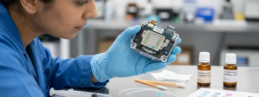
How Do I Clean a Severely Clogged UV Printhead?
The industrial standard operating procedure for reviving dried, missing, or deflected nozzles: chemical triage, reverse vacuum back-flushing, ultrasonic safety boundaries, and curtain diagnostics.
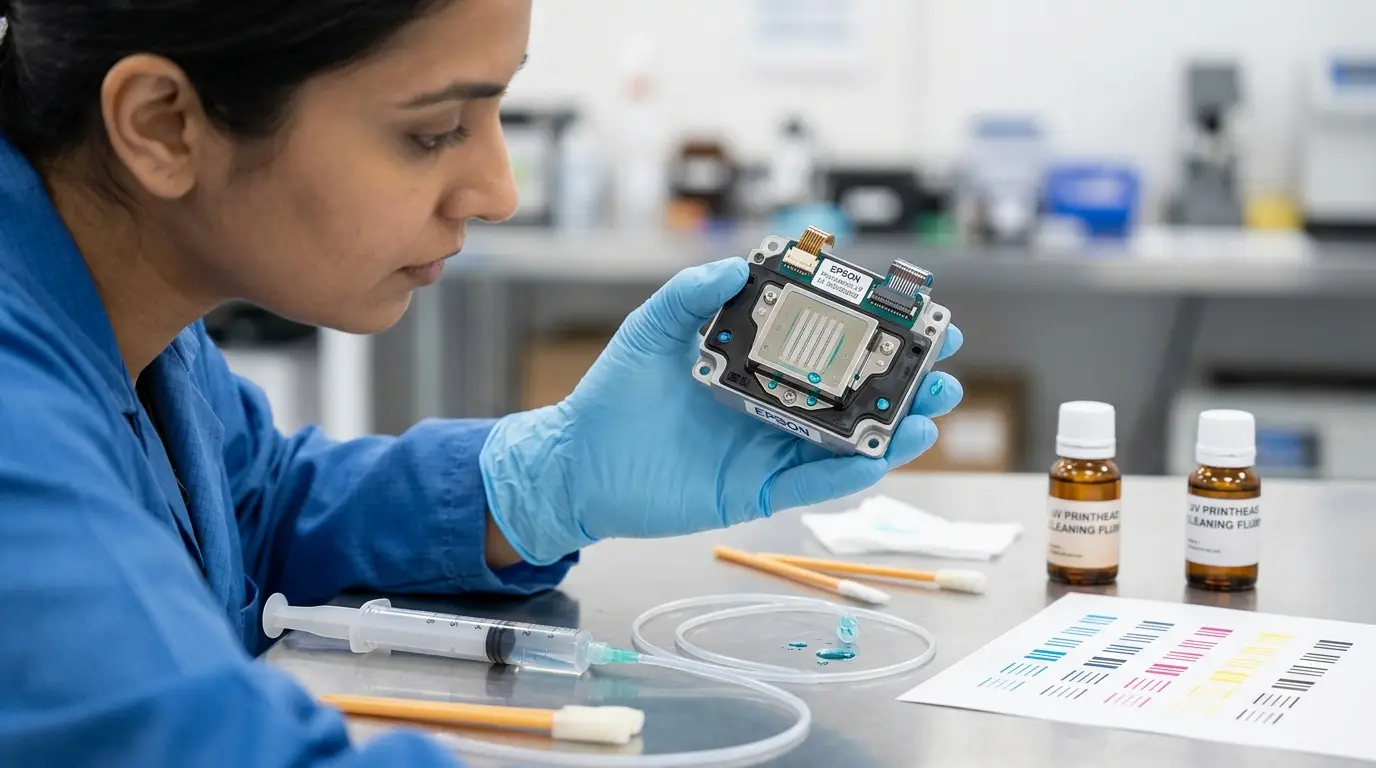
1. The Chemistry of a UV Clog: Soft Sludge vs. Irreversible Cure
Before attempting any mechanical or chemical intervention on an Epson (i3200, XP600, DX5/DX7), Ricoh (Gen5/Gen6), or Toshiba printhead, you must understand the underlying physics of UV-curable ink. UV ink does not dry through liquid solvent evaporation. It consists of liquid monomer oligomers, color pigments, and photoinitiators engineered to instantly form rigid, crosslinked thermoset plastic polymers when hit by 395nm ultraviolet light.
Printhead clogs fall strictly into two categories, and their recovery prospects are fundamentally distinct:
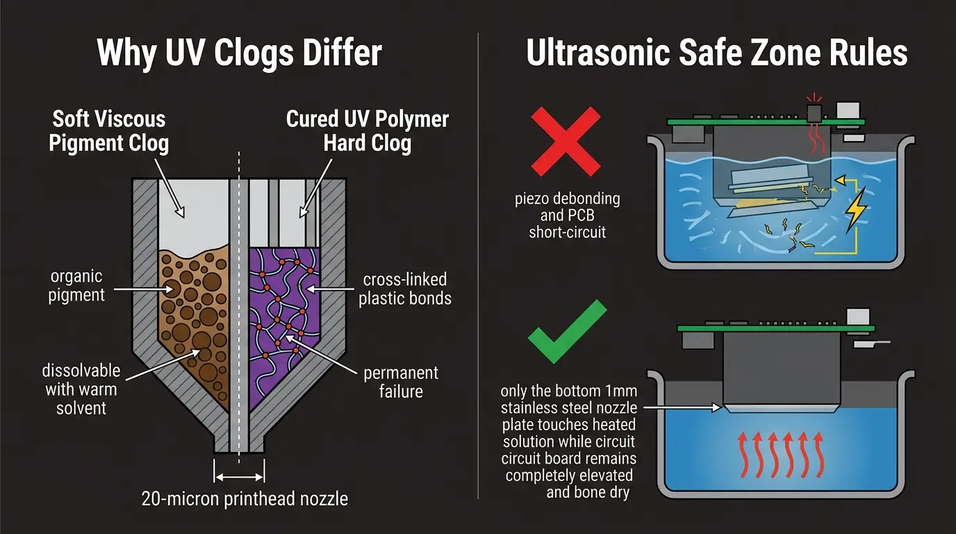
Pigment Sedimentation & Viscous Thickening
Occurs when the printer sits un-capped or idle in dark conditions. Inorganic pigments (especially titanium dioxide in white channels) settle into dense clay-like paste, or volatile monomer traces slowly gel into sticky syrup.
Verdict: 100% Recoverable. Can be fully liquefied and cleared using warm specialized recovery flushes and reverse pressure.
Cross-Linked Cured Thermoset Resin
Occurs when stray UV lamp reflections bounce off highly reflective media (mirrors, polished chrome, clear acrylic) back onto the nozzle plate, or when the printer is exposed to ambient sunlight through open windows.
Verdict: Permanently Dead. The monomers have formed covalent carbon-carbon molecular bonds. Any chemical strong enough to dissolve cured UV plastic will dissolve the printhead internal adhesives first.
2. The 4 Deadly Mistakes That Destroy Clogged Printheads
In panic, unassisted operators frequently turn a recoverable /bin/zsh maintenance issue into a ,000 replacement bill within 60 seconds. Eliminate these fatal mistakes immediately:
Using Drugstore Isopropyl Alcohol (IPA) or Acetone
Standard 70% or 99% isopropyl alcohol penetrates the interior epoxy seals holding the micro-piezo ceramic actuators to the nozzle plate. Within hours, it causes internal seal delamination, mixing ink channels together. Acetone instantly melts plastic manifolds and dissolves internal fluoropolymer gaskets.
Vigorous Forward Syringe Pushing ("The Hydraulic Ram")
Jamming a syringe onto an inlet nipple and bearing down with full body weight creates hydraulic pressures exceeding 40 PSI (2.7 bar). Printhead micro-nozzle membranes are rated for under 5 to 7 PSI. Excessive forward pressure ruptures the delicate internal filter mesh and blows the nozzle plate right off its silicon substrate.
Full Submergence in an Ultrasonic Jewelry Cleaner
Dumping an entire printhead into an ultrasonic bath is fatal. Ultrasonic cavitation tears the microscopic wire bonds on piezoelectric crystals, while cleaning solvent seeping onto the printed circuit board (PCB) leaves conductive residue that short-circuits the mainboard upon power-up.
Wiping with Standard Cotton Swabs or Paper Towels
Grocery store cotton swabs and industrial paper towels shed microscopic wood and cotton fibers that snag on the razor-sharp 20-micron orifice edges. Furthermore, their rough cellulose fibers scratch the microscopic hydrophobic coating that prevents ink mist pooling.
3. The 4-Stage Triage Escalation SOP (From Gentle to Intensive)
Always begin with the gentlest non-invasive procedure. Only escalate to mechanical intervention if lower-tier steps fail to clear missing nozzles.
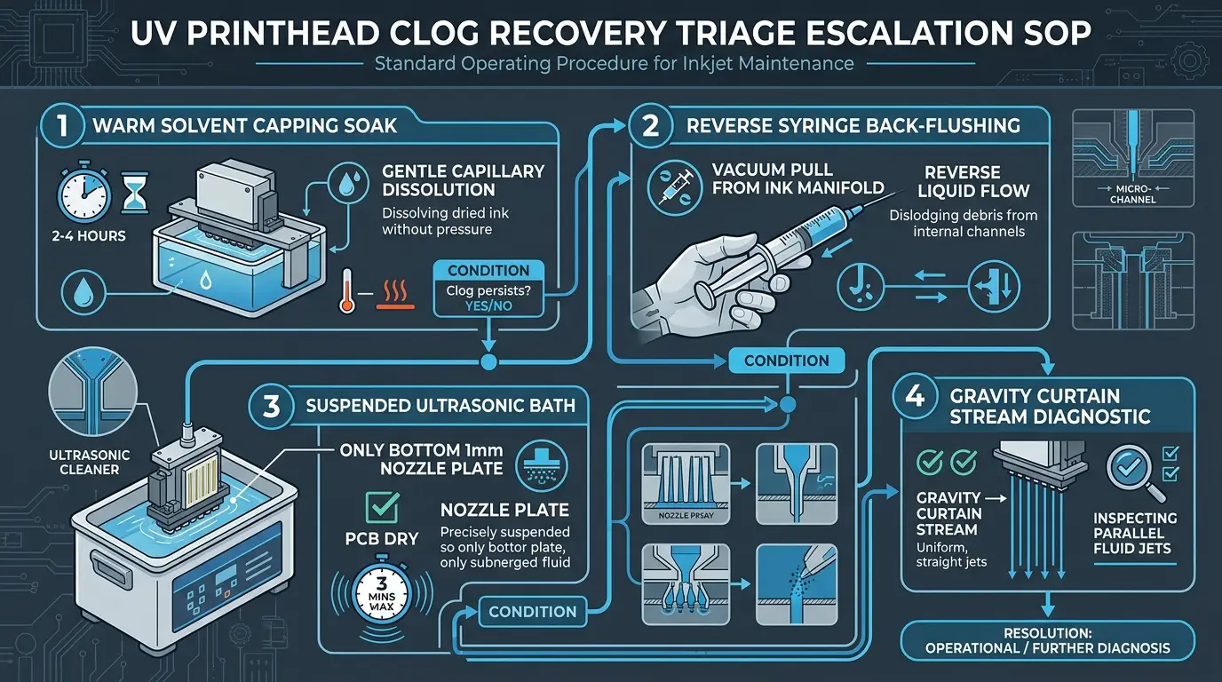
Gentle Capillary Dissolution (Zero Disassembly)
This procedure works while the printhead remains fully mounted inside the printer carriage:
- Step 1: Warm 30ml of specialized UV cleaning flush to 45°C (113°F) by placing the solvent container into a warm water bath.
- Step 2: Move the carriage away from the capping station. Clean the capping station perimeter rubber seal with a cleanroom polyurethane foam swab.
- Step 3: Fill the capping rubber cup to the brim with the heated UV cleaning solution.
- Step 4: Manually park the carriage back onto the capping station until you verify an airtight perimeter seal.
- Step 5: Clamp the waste ink drain tube with a plastic clip to prevent the cleaning solution from draining away via siphon action.
- Step 6: Allow the nozzle plate to sit submerged in the warm liquid for 2 to 4 hours. Unclamp the tube, perform one standard software cleaning cycle, and print a nozzle check.
Drawing Debris Out Instead of Pushing It In
If nozzles remain missing after Level 1, remove the ink dampers from the printhead inlet nipples to prepare for reverse extraction:
- Step 1: Pour 5mm of warm UV flush into a shallow clean glass petri dish. Rest the printhead nozzle plate gently into the fluid (do not submerge side electronics).
- Step 2: Connect a 20ml Luer-lock syringe to a 10cm piece of medical-grade silicone tubing (internal diameter ~2.5mm to 3.0mm, matched tightly to the printhead ink post).
- Step 3: Slip the tubing snugly over the inlet nipple of the clogged channel.
- Step 4: PULL BACKWARD GENTLY on the syringe plunger to create a steady -2 to -3 PSI vacuum. You will see colored ink, viscous sludge, and micro-particles drawn out of the head into the syringe barrel.
- Step 5: Discard the extracted sludge. Repeat this reverse vacuum pull 3 to 4 times per channel. Never push the dirty fluid back into the head!
Suspension Fixture: Only Bottom 1–2mm In Solution
Ultrasonic treatment is an intensive measure reserved for stubbornly hardened nozzles. It requires strict adherence to physical boundaries:
- Safety Rule 1: Fill the ultrasonic cleaner with distilled water heated to 40°C. Place a small shallow glass beaker containing 5mm of UV recovery solution inside the water bath (indirect sonication).
- Safety Rule 2: Use a mechanical clamp or custom jig to suspend the printhead. Only the bottom 1.0mm to 1.5mm of the stainless steel nozzle plate may touch the solution.
- Safety Rule 3: The upper manifold, casing screws, ribbon cable connectors, and internal circuit board must remain completely elevated and 100% bone dry.
- Safety Rule 4: Activate low-power sonication (35kHz–40kHz) for exactly 90 seconds. Turn off the unit, pause for 60 seconds, and run a second 90-second pulse. Never exceed 5 minutes total sonication time.
The "Nozzle Waterfall" Flow Verification
After completing Level 2 or Level 3, verify nozzle clearing before reinstalling the head into the carriage:
- Execution: Fill a clean syringe with 5ml of room-temperature clear UV cleaning flush. Attach it to the ink post. Hold the printhead horizontally above a collection beaker.
- Observation: Depress the plunger using gentle thumb pressure (less than 3 PSI). Look directly at the bottom nozzle face.
- Healthy Result: A perfect, uniform "waterfall" or sheet of hundreds of parallel vertical micro-jets spraying straight down with zero divergence.
- Deflected Result: Jets spraying sideways at odd angles indicate microscopic residue clinging to the nozzle exit perimeter. A quick wipe with a cleanroom foam swab soaked in flush usually corrects this.
4. Comprehensive Recovery Method Comparison
Review the risk profile, time commitment, and success probabilities across all four intervention techniques:
| Recovery Method | Target Clog Severity | Time Required | Success Rate | Risk to Printhead |
|---|---|---|---|---|
| Warm Capping Soak | Mild to moderate surface crusting | 2 to 4 hours | 70% – 80% | Zero risk (in-chassis) |
| Reverse Syringe Vacuum | Heavy sludge & particulate settling | 15 to 30 minutes | 80% – 90% | Very Low (if gentle vacuum used) |
| Suspended Ultrasonic Meniscus | Stubborn, dried white pigment clogs | 3 to 5 minutes | 50% – 65% | Moderate (high risk if submerged) |
| Forward High-Pressure Flush | Desperation tactic (NOT RECOMMENDED) | 2 minutes | < 15% | Critical (internal membrane burst) |
5. The Post-Recovery Re-Commissioning SOP
Many operators recover a printhead successfully, only to have it re-clog within 15 minutes of reinstallation because they rushed the re-commissioning process:
Install Brand New Dampers Before Connecting Inks
Never reconnect old ink dampers to a newly recovered printhead. Dampers are cheap disposable consumables (– each) containing internal fine mesh screens that harbor the exact dried debris that caused the initial clog. Always install clean dampers.
Purge Flushing Fluid Completely Out of Internal Manifolds
Cleaning flush lowers the surface tension and viscosity of UV ink. If residual solvent remains inside the printhead, ink will bleed across nozzle channels and drip uncontrollable onto the platen. Draw fresh ink through the damper until pure ink fills the manifold.
Observe the Essential 30-Minute Micro-Bubble Rest Period
Syringe pumping and fluid flushing introduce microscopic air bubbles into the piezo firing chambers. If you fire the printhead immediately, these compressible micro-bubbles act like shock absorbers, causing missing nozzles that mimic clogs. Park the carriage on a moist capping station and let it rest undisturbed for 30 minutes before firing.
6. Low-Maintenance Hardware Platforms Engineered for Clog Prevention
The ultimate defense against printhead clogs is choosing hardware with built-in active white ink agitation, timed automated circulation loops, and industrial capping systems:
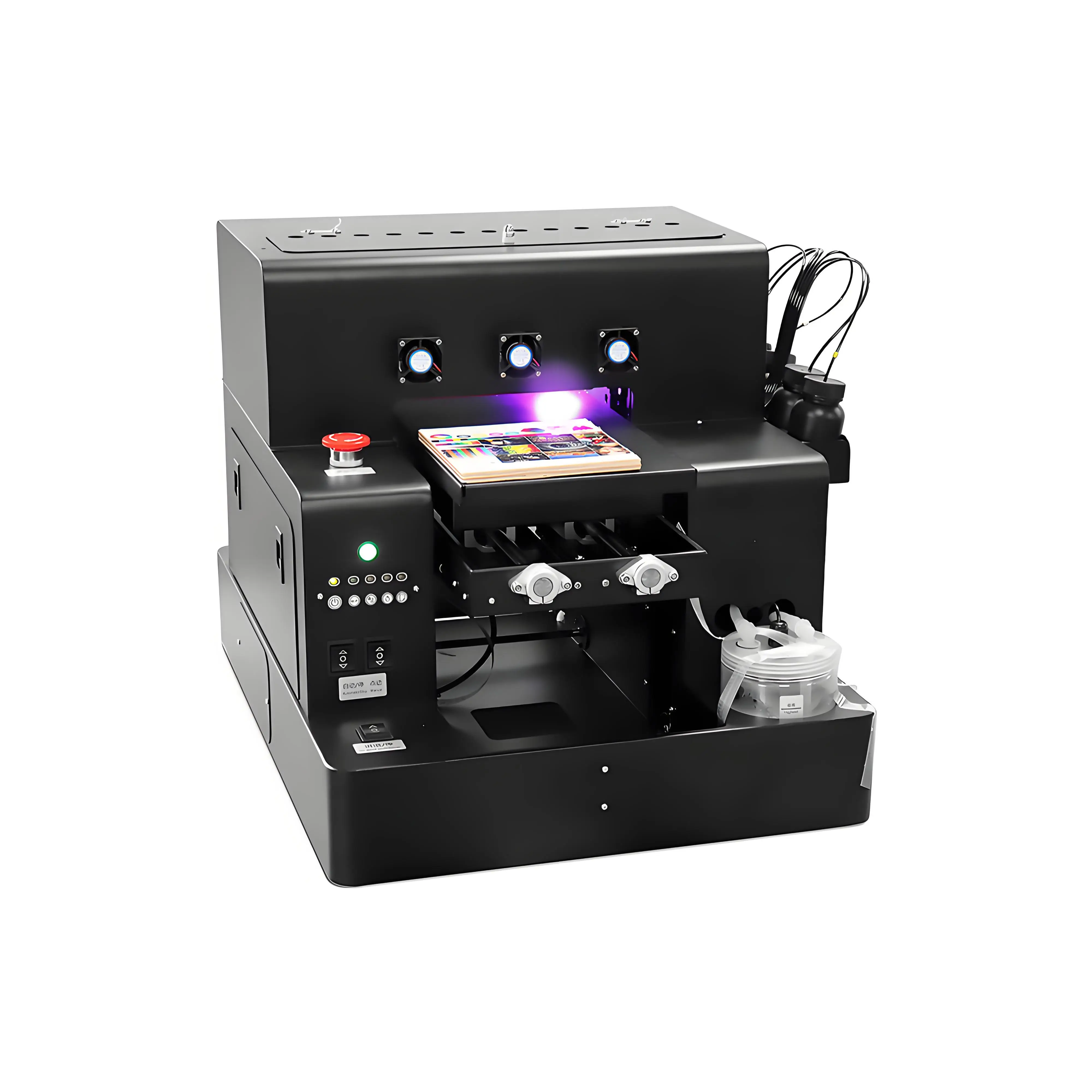
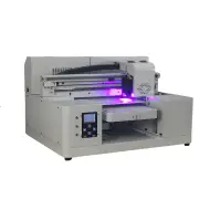
Spot A4 LED UV Printer Cylinder Printing Machine
- Automated white ink circulation system runs on scheduled timers to prevent TiO2 pigment settling and damper clogs
- Precision infrared substrate height detection prevents accidental head strikes and nozzle plate damage
- Cold water-cooled 395nm UV LED curing lamp reduces heat radiation onto the printhead nozzle face
- Modular rotary attachment included for bottles, tumblers, and cylindrical drinkware
- Accessible capping station assembly allows effortless 2-minute daily moisturizing maintenance
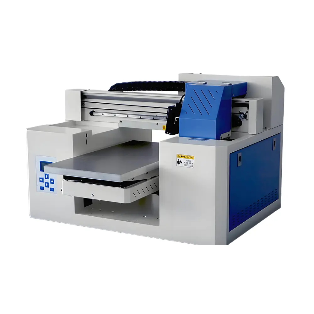
A3 Dual Head UV Printer (Rotary & UV DTF Support)
- Dual independent Epson printheads physically isolate White channels from Color/Varnish, eliminating cross-contamination
- Continuous secondary ink circulation loops with high-flow peristaltic pumps keep heavy white pigments suspended
- Integrated negative pressure vacuum suction platen secures thin film substrates firmly without curling
- Motorized 15 cm Z-axis clearance supports custom gift boxes, tumblers, wood plaques, and phone cases
- Dual capability: direct flatbed printing + rotary cylindrical items + peel-and-stick UV DTF transfers
Frequently Asked Questions (FAQ)
Q1. Can a completely dry or rock-hard UV printhead clog ever be recovered?
It depends strictly on whether the ink cured from UV light exposure or simply dried from air and pigment sedimentation. If liquid monomers were struck by stray UV radiation or direct window sunlight, they cross-link into permanent polymerized plastic that cannot be chemically dissolved without destroying the printhead itself. However, if the clog is caused by heavy pigment settling (such as titanium dioxide sludge in white channels) or viscous resin crusting from air drying, it can almost always be recovered using warm specialized recovery flush and reverse syringe suction.
Q2. Why is medical rubbing alcohol (IPA) dangerous for cleaning UV printheads?
Standard 70% or 91% isopropyl alcohol attacks the internal structural epoxy resin that seals the delicate piezoelectric actuators to the microscopic nozzle plate. Prolonged exposure causes internal delamination, leading to catastrophic channel cross-bleeding and electrical shorts. Furthermore, alcohol strips the hydrophobic fluoropolymer coating on the nozzle face, causing ink droplets to pool and misdirect during printing.
Q3. What is reverse syringe flushing and why is it safer than forward pushing?
In forward pushing, injecting cleaning fluid down into the ink inlet pushes dried pigment flakes and particulate matter directly into the microscopic 20-micron nozzle apertures, wedging them tighter or tearing the internal filter mesh. Reverse flushing pulls a gentle vacuum from the inlet nipple with a syringe while the nozzle plate sits in warm cleaning solution, drawing debris backwards away from the tiny orifices.
Q4. How long should a clogged printhead soak in cleaning solution?
A standard warm solvent capping soak (Level 1) should last between 2 and 4 hours. For severe clogs, an overnight soak of 8 to 12 hours is acceptable, provided you use specialized non-drying moisturizing recovery fluid rather than fast-evaporating aggressive flush. Never leave a printhead submerged in aggressive flush for more than 24 hours, as prolonged chemical attack softens internal seals.
Q5. Is an ultrasonic cleaner safe for Epson and industrial UV printheads?
Ultrasonic baths must be used with extreme caution. Never fully submerge a printhead in an ultrasonic cleaner. Cavitation waves will shatter microscopic piezoelectric crystal wire bonds and fluid will permanently short-circuit the electronic PCB. Only suspend the printhead so that the bottom 1 to 2 millimeters of the stainless steel nozzle plate contacts heated cleaning liquid, running low-frequency cycles for no more than 3 to 5 minutes.
Q6. What temperature should the cleaning solution be for optimal clog removal?
Warm cleaning flush heated to 40°C to 50°C (104°F to 122°F) dramatically accelerates the dissolution of viscous acrylate monomers and dissolves dried pigment clusters up to 300% faster than room-temperature solvent. Never exceed 55°C (131°F), as excessive heat can deform delicate internal plastic manifolds and micro-valves.
Q7. What is the 'nozzle waterfall' test and what does it tell me?
The nozzle waterfall or curtain test involves connecting a syringe of cleaning fluid to the printhead inlet nipple and applying gentle, steady downward pressure while observing the spray pattern exit the nozzle plate. A healthy head produces dozens of perfectly vertical, parallel micro-jets resembling a uniform waterfall curtain. Crooked or diagonal jets indicate partial nozzle rim clogs, while gaps indicate completely blocked channels.
Q8. Why do white UV ink channels clog so much more severely than CMYK colors?
White UV ink contains heavy inorganic titanium dioxide (TiO2) particles, which have roughly triple the mass and density of organic color pigments. Without active circulation, TiO2 precipitates out of suspension within 48 to 72 hours, forming a dense, chalky clay-like sludge inside ink dampers, micro-tubing, and printhead internal filter screens.
Q9. When should I stop attempting recovery and replace the printhead instead?
If a printhead has missing nozzles in identical locations despite 3 rounds of reverse suction and heated soaking, if fluid injected into one color port leaks out of an adjacent color nozzle row (internal delamination), or if the electrical resistance test reads shorted/blown transistors, the printhead is mechanically or electrically dead and must be replaced.
Q10. How do I safely re-install a recovered printhead to prevent instant re-clogging?
Before re-mounting the recovered printhead, install brand-new ink dampers and flush the ink feed lines. Draw 10ml of fresh UV ink through each damper with a syringe to eliminate air pockets, purge out all residual cleaning flush from the head, park it on a moist capping station, and let it rest undisturbed for 30 to 60 minutes to allow ink micro-bubbles to settle before running a test print.